
| Lifting method |  |  |  |  |  |  |  |  |
Number
Lifting angle | 1 | 2 | 1 | 2 | 2 | 2 | 3/4 | 3/4 |
| 0° | 0° | 90° | 90° | 0-45° | 45-60° | asymmetric | 0-45° | 45-60° | asymmetric |
| M | Working limit load/T |
| 8×1.25 | 0.8 | 1.6 | 0.5 | 1.0 | 0.70 | 0.5 | 0.5 | 1.05 | 0.75 | 0.5 |
| 10×1.50 | 12 | 2.4 | 0.7 | 1.4 | 0.98 | 0.7 | 0.7 | 1.47 | 1.05 | 0.7 |
| 12×1.75 | 2.0 | 4.0 | 1.0 | 2.0 | 1.40 | 1.0 | 1.0 | 2.10 | 1.50 | 1.0 |
| 14×2.00 | 2.4 | 4.8 | 1.5 | 30 | 2.10 | 1.5 | 1.5 | 3.15 | 2.25 | 1.5 |
| 16×2.00 | 3.2 | 6.4 | 2.0 | 4.0 | 280 | 2.0 | 20 | 4.20 | 3.00 | 2.0 |
| 18×2.50 | 5.0 | 10.0 | 2.5 | 5.0 | 3.50 | 2.5 | 2.5 | 5.25 | 3.75 | 2.5 |
| 20×2.50 | 5.6 | 11.2 | 3.0 | 6.0 | 4.20 | 3.0 | 3.0 | 6.30 | 4.50 | 3.0 |
| 22×2.50 | 7.0 | 14.0 | 4.0 | 8.0 | 5.50 | 4.0 | 4.0 | 8.00 | 6.00 | 4.0 |
| 24×3.00 | 9.2 | 18.4 | 5.0 | 10.0 | 7.00 | 5.0 | 5.0 | 10.50 | 7.50 | 5.0 |
| 27×3.00 | 9.5 | 19.0 | 5.6 | 11.2 | 7.84 | 5.6 | 5.6 | 11.76 | 8.40 | 5.6 |
| 30×3.50 | 12.0 | 24.0 | 78 | 15.6 | 10.92 | 78 | 7.8 | 16.38 | 11.70 | 78 |
| 36×4.00 | 13.0 | 26.0 | 10.0 | 20.0 | 14.00 | 10.0 | 10.0 | 21.00 | 15.00 | 10.0 |
| 36×4.00 | 14.0 | 28.0 | 11.5 | 23.0 | 16.30 | 11.5 | 11.5 | 24.30 | 17.20 | 11.5 |
| 42×4.50 | 16.0 | 32.0 | 15.6 | 31.2 | 21.80 | 15.6 | 15.6 | 32.80 | 23.40 | 15.6 |
| 48×5.00 | 20.0 | 40.0 | 20.0 | 40.0 | 28.00 | 20.0 | 20.0 | 42.00 | 30.00 | 20.0 |
| 56×5.50 | 22.0 | 44.0 | 22.0 | 44.0 | 30.80 | 22.0 | 220 | 46.20 | 33.00 | 22.0 |
| 64×6.00 | 22.5 | 45.0 | 22.5 | 45.0 | 31.50 | 22.5 | 22.5 | 47.25 | 33.75 | 225 |
Metric Thread
| WLL/T | M | Technical Parameter mm | Nm | Kg |
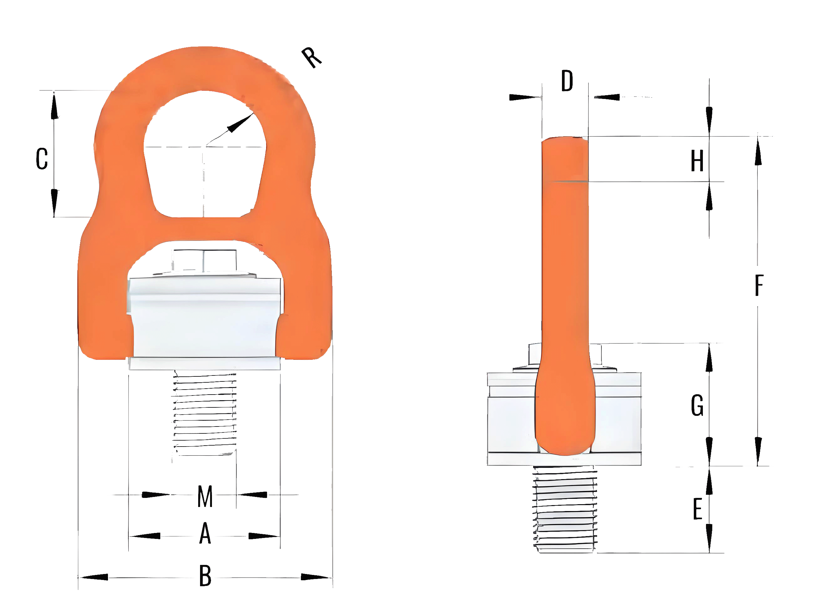
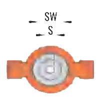
| E | A | B | C | D | F | G | H | R | S | SW |
| 0.5 | 8×1.25 | 12 | 33 | 58 | 36 | 10.0 | 84 | 300 | 10 | 15.5 | 6 | 13 | 10 | 0.32 |
| 0.7 | 10×1.50 | 15 | 33 | 58 | 36 | 10.0 | 84 | 30.0 | 10 | 15.5 | 6 | 13 | 10 | 0.32 |
| 1.0 | 12×1.75 | 20 | 33 | 58 | 36 | 10.0 | 84 | 30.0 | 10 | 15.5 | 6 | 13 | 15 | 0.33 |
| 1.5 | 14×2.00 | 21 | 50 | 90 | 50 | 15.0 | 125 | 44.0 | 18 | 22 | 8 | 19 | 30 | 1.15 |
| 2.0 | 16×2.00 | 24 | 50 | 90 | 50 | 15.0 | 125 | 44.0 | 18 | 22 | 8 | 19 | 50 | 120 |
| 2.5 | 18×2.50 | 26 | 65 | 117 | 66 | 22.0 | 163 | 58.0 | 21 | 29.5 | 10 | 27 | 70 | 2.60 |
| 3.0 | 20×2.50 | 30 | 65 | 117 | 66 | 22.0 | 163 | 58.0 | 21 | 29.5 | 10 | 27 | 100 | 2.65 |
| 4.0 | 22×2.50 | 33 | 65 | 117 | 66 | 22.0 | 163 | 58.0 | 21 | 29.5 | 10 | 27 | 100 | 2.70 |
| 5.0 | 24×3.00 | 36 | 65 | 117 | 66 | 22.0 | 163 | 580 | 21 | 29.5 | 10 | 27 | 160 | 2.75 |
| 5.6 | 27×3.00 | 38 | 87 | 147 | 80 | 26.5 | 196 | 76.5 | 28 | 35.5 | 14 | 34 | 200 | 5.45 |
| 7.8 | 30×3.50 | 48 | 87 | 147 | 80 | 26.5 | 196 | 76.5 | 28 | 35.5 | 14 | 34 | 500 | 5.50 |
| 9.0 | 36×4.00 | 54 | 87 | 147 | 80 | 26.5 | 196 | 76.5 | 28 | 35.5 | 14 | 34 | 500 | 5.60 |
| 11.5 | 36×4.00 | 56 | 110 | 186 | 100 | 33.0 | 256 | 95.0 | 36 | 44 | 19 | 46 | 600 | 11.55 |
| 15.6 | 42×4.50 | 63 | 110 | 186 | 100 | 33.0 | 256 | 95.0 | 36 | 44 | 19 | 46 | 600 | 11.80 |
| 20.0 | 48×5.00 | 72 | 110 | 186 | 100 | 33.0 | 256 | 95.0 | 36 | 44 | 19 | 46 | 600 | 12.10 |
| 220 | 56×5.50 | 84 | 123 | 200 | 110 | 35.0 | 279 | 107.0 | 36 | 48.5 | 22 | 55 | 800 | 15.90 |
| 22.5 | 64×6.00 | 100 | 123 | 200 | 110 | 35.0 | 279 | 107.0 | 36 | 48.5 | 22 | 55 | 800 | 16.70 |
★ Safetyfacto 4:1;Bolt length and thread specifications can be made acording to requirements. B is the general structure, S is the small body structure.
Unc Thread
| WLL/T | Technical Parameter mm | Nm | Kg |
| M | TPI | E | A | B | C | D | F | G | H | R | S | SW |
| 0.80 | 1-2 | 13.0 | 20 | 33 | 58 | 36 | 10.0 | 84 | 30.0 | 10 | 15.5 | 6 | 13 | 15 | 0.33 |
| 1.60 | 5-8 | 11.0 | 24 | 50 | 90 | 50 | 15.0 | 125 | 44.0 | 18 | 22.0 | 8 | 19 | 30 | 1.20 |
| 2.40 | 3-4 | 10.0 | 30 | 65 | 117 | 66 | 22.0 | 163 | 58.0 | 21 | 29.5 | 10 | 27 | 80 | 2.60 |
| 3.00 | 7-8 | 9.0 | 36 | 65 | 117 | 66 | 22.0 | 163 | 58.0 | 21 | 29.5 | 10 | 27 | 90 | 2.65 |
| 4.00 | 1 | 8.0 | 36 | 65 | 117 | 66 | 22.0 | 163 | 58.0 | 21 | 29.5 | 10 | 27 | 110 | 2.75 |
| 6.25 | 1-1/4 | 7.0 | 48 | 87 | 147 | 80 | 26.5 | 196 | 76.5 | 28 | 35.5 | 14 | 34 | 200 | 5.55 |
| 10.00 | 1-1/2 | 6.0 | 60 | 110 | 186 | 100 | 33.0 | 256 | 95.0 | 36 | 44.0 | 19 | 46 | 500 | 11.30 |
| 16.00 | 2 | 4.5 | 76 | 110 | 186 | 100 | 33.0 | 256 | 95.0 | 36 | 44.0 | 19 | 46 | 600 | 13.20 |
★ Safety factor 4:1;Bolt length and thread specifications can be made according to requirements


