Structure
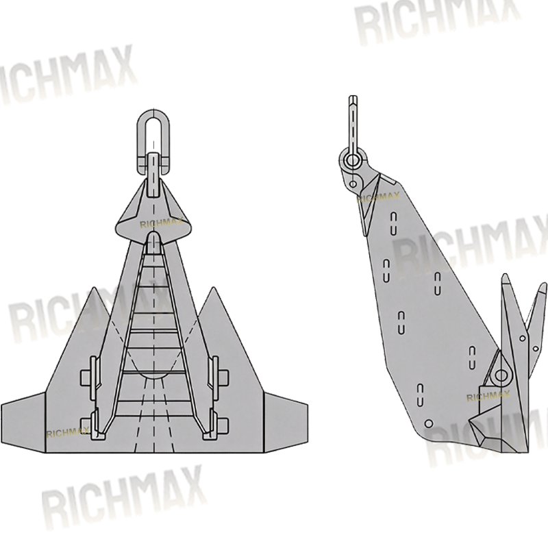
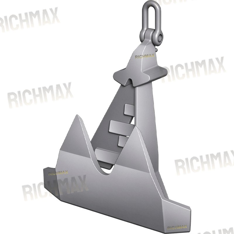
The Stevpris MK5 HHP Anchor is designed for high holding power applications where anchor geometry, seabed penetration and load transfer must work together. Its main structural components include the shank, fluke assembly, connecting pins, pin seats and shackle connection. Each component has a specific function in positioning the anchor, engaging the seabed and transferring mooring loads through the anchor body.
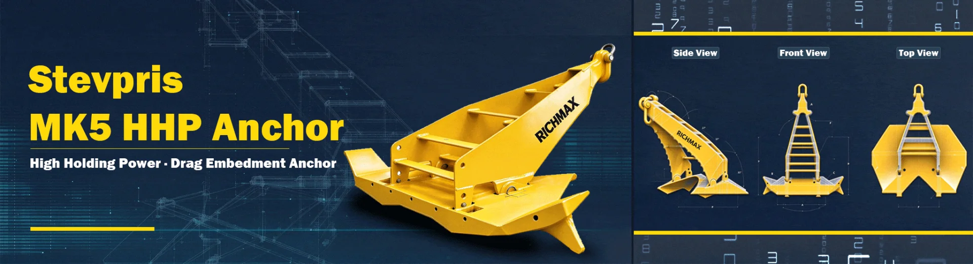
1. Modular Anchor Assembly
The anchor consists of several major components assembled through designated mechanical connections. Depending on the supplied configuration, the assembly may include a separate shank and fluke section, primary and secondary pins, and a shackle connection seat.
A sectional design can simplify transportation, storage and handling of large anchor components. It may also reduce the need for major assembly work at the installation site, provided the anchor is supplied with the required pins, locking arrangements and assembly instructions.
The fit between the shank, fluke assembly and connecting pins is important. Excessive clearance can cause unwanted movement and uneven contact under load, while insufficient clearance may restrict the intended articulation. Machining tolerances, pin dimensions and assembly checks should therefore follow the approved manufacturing drawings.
2. Shank Design and Load Transfer
The shank connects the mooring line to the working section of the anchor. Its geometry and stiffness affect how the applied load is transferred to the flukes during penetration and holding.
A streamlined shank profile can reduce hydrodynamic resistance during deployment and retrieval. Its shape also affects how the anchor passes over the stern roller and through the associated handling arrangement. The actual clearance depends on the anchor dimensions, vessel equipment and handling procedure.
Reinforced sections around the shank and its pin connections help carry the loads specified in the design. The load path must remain consistent with the approved geometry, including the alignment of the shank, pin seats and fluke assembly. Local deformation or wear at these interfaces can affect movement and load distribution.
3. Fluke Geometry and Seabed Penetration
The flukes are the main seabed-engaging components. Their width, curvature, tip geometry and working angle influence initial penetration and the resistance developed as the anchor is pulled into the seabed.
A broad, curved fluke provides a substantial soil-engaging surface. A pointed or toothed leading edge, where included in the specified design, helps the tip enter suitable seabed materials. Penetration still depends on soil strength, seabed layering, anchor orientation and the applied loading conditions.
Some configurations may incorporate a hollow fluke section designed to accommodate ballast blocks. Additional ballast changes the anchor's weight and initial contact with the seabed, but it does not guarantee penetration in every ground condition. Its use should be confirmed against the manufacturer's configuration and the project requirements.
Where the design provides an adjustable shank-to-fluke angle, the setting can be selected for the intended seabed conditions. The available settings and adjustment procedure must be confirmed for the specific model. Any adjustment should use the designated pin positions and locking arrangements rather than site welding or unauthorised modification.
4. Centre of Gravity and Positional Stability
The distribution of mass across the shank, flukes and connecting components affects how the anchor settles after reaching the seabed. A suitably positioned centre of gravity can help the anchor assume its intended working orientation, while the fluke geometry and any designated stabilising features influence its behaviour during penetration.
Stability depends on more than anchor weight alone. The relationship between the centre of gravity, connection point, fluke geometry and direction of pull determines how the anchor responds as the mooring line is tensioned.
After penetration, the anchor must maintain the intended orientation under the loads specified for the mooring system. Resistance to rotation or overturning depends on the anchor design and seabed conditions. These characteristics should be assessed using the manufacturer's technical data and the applicable anchoring-system design basis.
5. Pins and Articulated Connections
The primary and secondary pins connect the relevant structural sections and allow the movement specified by the design. Their diameter, material, bearing surfaces, retention method and fit within the pin seats affect the reliability of the assembly.
Because these are load-bearing interfaces, inspection should cover pin wear, clearance, surface damage, deformation and the condition of the surrounding seats. Repeated loading and contact with abrasive seabed materials may contribute to wear over time.
The pin arrangement must also permit the required movement throughout the intended adjustment range. Poor dimensional control, incorrect assembly or damaged bearing surfaces may cause restricted movement, uneven loading or difficulty changing the working angle.
6. Reinforcement and Welded Joints
The shank, fluke body, pin seats and other load-bearing areas may incorporate reinforcing plates, stiffeners or locally increased plate thickness, depending on the approved design.
These features help resist the stresses associated with the specified loading conditions. Welded joints must be manufactured in accordance with the applicable drawings, welding procedures and acceptance criteria. Particular attention should be given to areas around pin seats, fluke roots, tips and other locations where loads are concentrated.
Inspection requirements may include visual examination, dimensional checks and non-destructive testing where specified by the purchase order, design documentation or classification requirements. Weld quality and reinforcement details should be verified against the approved manufacturing documents rather than assumed from external appearance.
7. Size Range and Handling Requirements
Anchor selection should be based on the required holding performance, design loads, seabed conditions, mooring arrangement and available installation equipment. Overall mass is only one selection parameter.
For larger anchors, the external dimensions and centre of gravity affect lifting arrangements, transport supports, storage space and handling over the vessel's stern roller. The vessel's lifting capacity, deck layout, roller dimensions and connection equipment should be checked before shipment and installation.
The available size range and weight of each configuration should be confirmed from the manufacturer's current product drawings and data sheets. Where an anchor is intended to replace an existing unit, dimensional compatibility and the connection interface should be checked before ordering.
8. Structural Limitations and Maintenance Considerations
The articulated connections require periodic inspection because pin wear and increasing clearance may develop under repeated loading and abrasive seabed contact. Inspection intervals should reflect the manufacturer's instructions, service conditions and the applicable maintenance plan.
A broad fluke is intended to engage suitable seabed materials. It should not be assumed to penetrate intact, hard rock effectively. In very hard ground, penetration may be limited, and the fluke tips may be exposed to impact or abrasion. Seabed suitability should be assessed during mooring-system design.
The modular assembly also depends on accurate manufacturing and correct installation. Dimensional errors, damaged pin seats, incorrect pin installation or unsuitable locking arrangements can restrict movement and affect the intended working geometry.
During retrieval, fluke tips and other projecting features may encounter rocks, abandoned equipment, seabed cables or pipelines. Such obstructions can complicate recovery and increase the risk of damage. Seabed clearance information and an appropriate recovery procedure should therefore be considered before retrieval.
For large anchor sizes, lifting, transport and storage require suitable load-rated equipment and adequate working space. The anchor's mass, dimensions and designated lifting points should be confirmed before handling.
Material
The material used for a Stevpris MK5 HHP Anchor must meet the structural, mechanical and environmental requirements of the intended anchoring system. The main body, flukes, shank, connecting components and pivot pins may require different material grades or manufacturing processes, depending on their functions and loading conditions.
Steel Strength and Toughness
The main structural components are manufactured from steel grades specified in the approved drawings and project requirements. The selected steel must provide the required tensile strength, toughness and ductility to withstand working loads, seabed contact and the impact conditions expected during anchor handling and deployment. For offshore applications, material selection should also consider cyclic loading and the specified operating temperature.
Wear Resistance of Critical Components
The anchor tip, fluke edges and other areas in contact with the seabed are exposed to abrasion from sand, gravel and other seabed materials. Their wear resistance depends on the steel grade, component thickness, structural design and any specified surface treatment. Pivot pins and other load-bearing connections require suitable mechanical properties to withstand shear forces, bearing pressure and repeated movement. Heat treatment or additional wear protection may be specified where required by the design.
Welding and Fabrication Quality
For welded anchor constructions, the base material, welding consumables and fabrication procedures must be compatible with the approved material specification. Qualified welding procedures, appropriate joint preparation and controlled welding conditions help maintain joint strength and reduce the risk of fabrication defects. Weld inspection should follow the project inspection plan, with additional non-destructive testing where specified.
Corrosion Protection
Steel anchors operating in marine environments require a surface protection system appropriate to their exposure conditions. Depending on the project specification, this may include surface preparation by abrasive blasting, a compatible marine coating system or other specified corrosion-control measures. Coating selection should account for immersion conditions, handling damage and expected contact with the seabed. Areas exposed to abrasion may require particular attention because coating damage can expose the underlying steel to seawater.
Material Certification and Traceability
Material certificates, heat numbers and inspection records should be maintained in accordance with the purchase specification and agreed quality plan. For projects requiring classification-society or third-party inspection, the applicable material certification, mechanical testing and inspection scope should be confirmed before production. These records help verify that the supplied materials and manufactured components conform to the specified requirements.
Material Considerations in Marine Service
Steel grade, fabrication quality and surface protection all affect the service performance of a Stevpris MK5 HHP Anchor. A higher-strength steel grade does not automatically provide better resistance to impact, fatigue or corrosion; these properties depend on the complete material specification and component design.
Protective coatings can reduce corrosion but may be damaged by handling, seabed contact or repeated abrasion. Exposed steel should therefore be inspected and repaired when necessary. Pivot pins and other moving connections also require periodic inspection for wear, corrosion and clearance changes, with lubrication or maintenance carried out where the design permits.
For offshore procurement, the material grade, mechanical properties, welding requirements, corrosion protection and inspection documentation should be defined in the technical specification. This allows the anchor to be manufactured and inspected against the actual service requirements rather than relying on assumptions based on the product name alone.
How To Use?
Stevpris MK5 HHP Anchor Installation, Operation and Maintenance
The Stevpris MK5 HHP Anchor is installed as part of an engineered offshore mooring system. Its performance depends on anchor configuration, seabed conditions, installation loads and the interaction between the anchor and the mooring line. Correct handling during deployment, installation verification and recovery is necessary to maintain structural integrity and achieve the required holding performance.
1. Pre-Installation Preparation
Before installation, check the anchor body, flukes, shank, pivot pins and connecting shackles for visible damage, deformation, cracks or other defects. Confirm that the anchor identification, weight, dimensions and connection arrangement correspond to the approved drawings and project specifications.
Seabed conditions should be assessed before selecting the anchor configuration. Fluke angle settings, where adjustable, must follow the manufacturer's approved configuration for the specific anchor model and intended ground conditions. Any additional ballast or configuration change must also be approved for the application rather than introduced as an improvised adjustment.
The installation team should verify the compatibility of the anchor, connecting shackles, mooring chain or wire, installation rigging and any specified chaser recovery system. Required inspection records, certificates and load limits should be available before offshore operations begin.
2. Anchor Deployment and Installation
The anchor is lowered from the anchor-handling vessel (AHV) using the designated handling equipment and approved installation procedure. Lowering speed should be controlled to prevent impact damage when the anchor reaches the seabed. The vessel's position, water depth and anchor touchdown location should be monitored throughout deployment.
After touchdown, the anchor is installed using the specified vessel movement and loading sequence. Controlled tension is applied through the installation line to allow the flukes to engage with the seabed and develop embedment. The applied load, vessel movement and installation response should be monitored against the project procedure.
Installation should not be considered complete solely because the anchor has reached the seabed or the mooring line has become tensioned. The required embedment, position and holding verification must be established using the acceptance criteria defined by the responsible project engineer or installation contractor.
3. Installation Verification and Holding Performance
Following installation, verify the anchor position and installation records against the approved mooring plan. Where required, prescribed loading tests, tension monitoring or other verification methods may be used to assess whether the anchor has achieved the specified installation condition.
Load application must remain within the approved limits for the anchor, connecting hardware and complete mooring system. Unexpected anchor movement, abnormal tension changes or failure to meet the specified acceptance criteria should be investigated before the system is accepted for service.
The holding capacity of an HHP anchor cannot be determined from its model designation or weight alone. Seabed strength, soil layering, embedment, loading direction and the overall mooring configuration all influence performance.
4. In-Service Monitoring
Once the mooring system is operational, monitor line tension and vessel or floating-unit position in accordance with the project monitoring plan. Changes in environmental loading, line tension or position may indicate a need for further assessment.
Underwater inspections should be carried out when required by the project, operating conditions or maintenance schedule. Depending on accessibility and the inspection scope, checks may cover exposed anchor components, connection points, corrosion protection and evidence of movement or damage.
Inspection findings and relevant operating data should be recorded so that changes in condition can be assessed over time. Any suspected anchor displacement or structural damage should be reviewed by the responsible engineering team before continued use is approved.
5. Anchor Recovery
Recovery should follow the approved procedure for the specific anchor configuration and seabed conditions. Where the design uses a chaser system, the specified recovery equipment is operated to engage the designated connection and release the anchor from its embedded position.
Recovery tension should be applied in a controlled manner and monitored throughout the operation. Excessive or sudden pulling loads can damage the anchor, connecting hardware or mooring line. If the anchor does not release as expected, the operation should be reassessed in accordance with the recovery procedure rather than continued through uncontrolled increases in tension.
Once recovered, remove accumulated seabed material and marine deposits using an appropriate cleaning method. Inspect the anchor body, flukes, pivot pins, connection points and protective coating for damage or abnormal wear. Any repair, lubrication or component replacement should follow the manufacturer's maintenance requirements.
6. Storage and Reuse
Before storage, record the anchor's condition and any defects identified during recovery. Support the anchor adequately on deck or in the storage area to prevent unintended movement, local impact and excessive loading on individual structural components.
Keep pivot areas and other moving components clean. Apply suitable lubricant where specified by the manufacturer, and protect exposed steel surfaces in accordance with the coating maintenance requirements.
Before reuse, confirm that the anchor remains compatible with the intended mooring arrangement and that any required inspection, repair or acceptance checks have been completed. Reuse should be based on the anchor's actual condition and applicable engineering requirements, not solely on its previous service history.
7. Operational Precautions
Incorrect configuration, uncontrolled deployment, excessive recovery tension and inadequate condition monitoring can affect anchor performance and damage load-bearing components. The anchor must be handled using equipment with suitable rated capacities and operated within the approved installation and recovery limits.
Personnel should remain clear of suspended loads, tensioned chains, wires and rigging during anchor-handling operations. Exclusion zones, communication arrangements and vessel procedures should be established before work begins. If abnormal movement, unexpected loading or equipment damage occurs, the operation should be stopped or made safe in accordance with the applicable offshore procedure before further assessment.
The Stevpris MK5 HHP Anchor should only be accepted for installation, service or reuse when its configuration, condition and performance satisfy the requirements of the approved mooring system.
Application
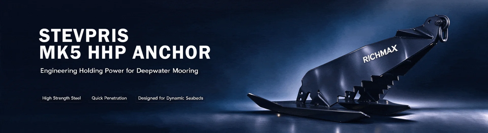
The Stevpris MK5 HHP Anchor is used in engineered offshore anchoring and mooring systems where an embedded anchor is required to resist the loads acting on a floating structure. Typical applications include offshore oil and gas facilities, mobile offshore units, floating construction equipment and other marine projects that require seabed anchoring.
Its suitability depends on the anchor design, seabed soil properties, required holding capacity, mooring-line configuration and installation conditions. The following applications represent potential uses where the anchor type is compatible with the project design.
Applications:
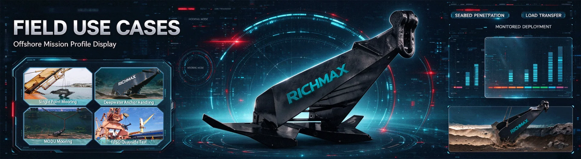
Permanent Mooring for Offshore Oil and Gas Facilities
Floating production, storage and offloading vessels (FPSOs), floating storage units (FSUs) and single-point mooring (SPM) systems may require seabed anchors to maintain their designated positions under wind, wave and current loads.
A Stevpris MK5 HHP Anchor may be considered for these systems when its holding performance and installation requirements meet the project specifications. Anchor capacity, line arrangement, fatigue-related loading and seabed conditions must be evaluated as part of the complete mooring-system design.
Temporary Mooring for Offshore Construction
Mobile offshore drilling units (MODUs), semi-submersible platforms, pipelay vessels, crane barges and dredging vessels may require temporary anchoring during drilling, installation, lifting or seabed construction work.
For these projects, the anchor must suit the operating period, expected environmental loads and planned installation and recovery procedures. Where recovery and reuse are required, the project should also consider anchor handling vessel availability, retrieval equipment and the feasibility of recovering the embedded anchor from the seabed.
Floating Offshore Renewable Energy
Floating offshore wind turbines and floating wave or tidal energy devices require mooring systems to control movement while accommodating environmental loads. Embedded high holding power anchors may be considered where the water depth, seabed conditions and mooring arrangement support their use.
For these applications, anchor selection must account for the site's geotechnical conditions, line direction, cyclic loading and the requirements of the complete floating system. Suitability should be established through project-specific engineering rather than inferred from the HHP designation alone.
Deepwater Aquaculture and Offshore Floating Platforms
Large offshore fish farms, deepwater net cages and floating aquaculture platforms may use seabed anchoring to maintain their positions in exposed marine environments.
A Stevpris MK5 HHP Anchor may be an option for a suitably engineered mooring arrangement, particularly where the project requires embedded anchors rather than conventional surface-based anchoring. The design must account for current-induced loads on nets and structures, environmental exposure, seabed conditions and the required service life.
Navigation Buoys and Marine Construction Floats
Large navigation buoys, pipeline protection marker buoys and temporary offshore construction floats may require anchoring to limit movement within a designated operating area.
The Stevpris MK5 is generally relevant only where the required holding capacity, installation method and equipment scale justify the use of a heavy-duty embedded anchor. Smaller buoys and conventional marine markers may be better served by lighter anchors designed for their specific loads and deployment arrangements.
Seabed Conditions and Application Limitations
Anchor performance depends on the interaction between the fluke geometry and the surrounding soil. Soft clay, cohesive seabed deposits and suitable sand formations may provide conditions for anchor penetration and embedment, but holding capacity varies with soil strength, density, layering and installation history. Calcareous soils and cemented seabeds require particular attention because their behaviour may differ significantly from that of conventional silica sand or clay.
The Stevpris MK5 HHP Anchor is not a universal solution for every seabed or loading direction. Several conditions require additional assessment before selection:
Hard, exposed bedrock: Where the anchor cannot penetrate the seabed, the required embedment and holding resistance may not develop. A different anchoring solution may be necessary.
Seabeds containing boulders or coarse rock layers: Obstacles may prevent proper penetration or cause the anchor to deviate from its intended installation path.
Areas with subsea pipelines, cables or dense underwater obstructions: Installation and recovery routes must be assessed to reduce the risk of snagging, equipment damage or interference with existing infrastructure.
Predominantly vertical loading: Embedded drag anchors are generally designed around a specified load direction and embedment mechanism. Significant uplift or an unsuitable line angle may reduce holding performance; the allowable loading direction must be verified against the approved anchor design.
Small vessels and routine harbour berthing: The anchor's size, handling requirements and need for suitable deployment and recovery equipment may make it impractical for ordinary vessel anchoring.
Before ordering a Stevpris MK5 HHP Anchor, the purchaser should confirm the required anchor weight and configuration, design holding capacity, seabed investigation data, mooring-line connection, installation method and recovery requirements. These details help determine whether the anchor is suitable for the intended project rather than relying on the product designation alone.
How To Choose?
Key Factors in Selecting a Stevpris MK5 HHP Anchor
Selecting a Stevpris MK5 HHP Anchor requires an assessment of seabed conditions, design loads, installation arrangements and the complete mooring system. The anchor weight and configuration should be determined from project-specific engineering data rather than general rules or previous experience alone.
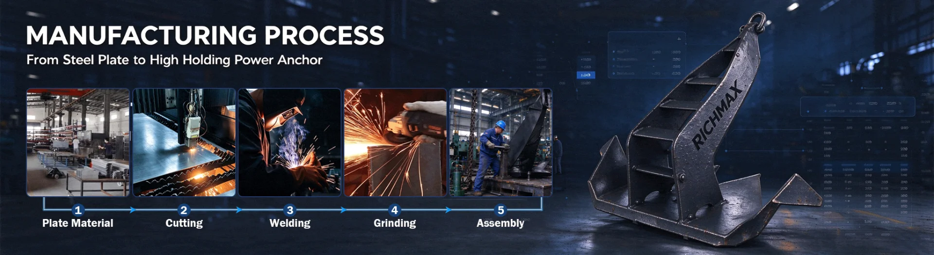
Our Manufacturing Process:
1. Evaluate Seabed Soil Conditions
Seabed conditions directly affect anchor penetration and holding capacity. Soil investigation reports should be reviewed to identify the soil type, strength profile, layer distribution and any site conditions that may restrict penetration.
The required fluke angle and anchor configuration should be selected according to the manufacturer's approved design and the project's geotechnical assessment. Different configurations may be considered for soft mud, ordinary clay, sand, dense sand or hard clay, but the appropriate angle cannot be determined from soil descriptions alone. Where the seabed is particularly dense or penetration is restricted, the need for additional ballast or an alternative anchoring arrangement should be assessed by the responsible engineer.
Rock, exposed bedrock and seabeds containing large boulders require particular attention. Increasing anchor weight does not necessarily solve a penetration problem, and an alternative anchoring method may be needed.
2. Calculate the Required Holding Capacity
Anchor selection should start with the design loads of the complete mooring system. For permanent offshore installations, the engineering assessment may need to account for extreme environmental conditions, including the project-specified wind, wave and current loads, together with line tensions, load directions and applicable design factors.
The required holding capacity should then be compared with the verified performance data for the proposed Stevpris MK5 anchor configuration under relevant seabed conditions. Anchor weight and holding capacity are related, but they are not directly interchangeable. A nominal holding-to-weight ratio should only be used when supported by applicable design data or validated performance information.
The final anchor weight should provide the required design capacity with the safety margins specified for the project. It should not be selected solely by applying a general ratio or increasing the weight without checking soil compatibility.
3. Consider the Floating Structure and Service Period
The mooring requirements vary with the type of floating structure and its intended service period. Permanent installations, such as FPSOs and floating wind turbines, generally require a documented assessment of long-term environmental loading, mooring reliability, inspection arrangements and applicable approval requirements.
For temporary applications, such as drilling units or construction barges, the selection should reflect the planned operating period, expected environmental conditions, deployment frequency and recovery arrangements. Reusable anchors may be suitable where the design and operating procedures permit repeated deployment, but their condition and performance should be assessed before reuse.
The distinction between permanent and temporary service should be reflected in the design basis, material and inspection requirements, rather than treated as a simple choice between heavier and lighter anchors.
4. Check Water Depth and Installation Vessel Capability
Water depth and available installation equipment affect whether an anchor can be deployed, set and recovered as planned. Before selecting the anchor, confirm the availability and capability of the anchor-handling vessel (AHV), the required mooring-line handling equipment and any chaser system specified for installation or recovery.
For deepwater projects, the installation method, line arrangement, vessel capability, seabed approach and recovery procedure should be reviewed together. The anchor must be compatible with the planned handling arrangement, and the installation sequence should be supported by project procedures.
Recovery feasibility deserves particular attention when an anchor is intended for reuse or when the project requires eventual removal. An anchor that meets the holding requirements but cannot be recovered using the available equipment may create significant operational and project costs.
5. Verify Certification and Material Documentation
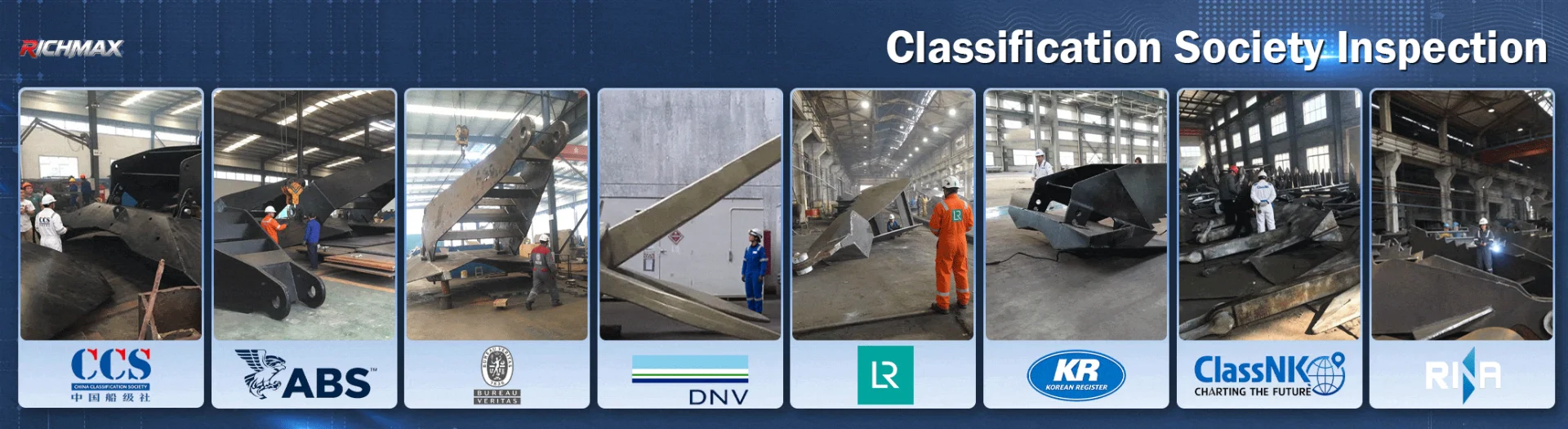
Certification requirements should be established before procurement. Depending on the project specification, these may include approval or inspection by DNV, ABS, Lloyd's Register (LR) or another designated organization, together with material test certificates (MTCs), inspection records and specified load-test reports.
Check that the documents correspond to the actual anchor supplied, including its model, identification number where applicable, material heat or batch traceability, weight and inspection status. The required certificate type and scope should be stated clearly in the purchase specification.
A certificate from a recognized organization should not be assumed to cover every component or every production stage. Confirm the scope of approval, applicable standard, inspection requirements and acceptance criteria before placing the order.
6. Match the Anchor to the Complete Mooring System
The Stevpris MK5 HHP Anchor should be selected as part of a complete load-bearing arrangement that includes the mooring chain or line, shackles, swivels and other specified connectors.
Connection dimensions, pin sizes, clearances, material grades and rated capacities must be compatible with the approved design. The allowable capacity of the complete load path should be checked so that no individual component becomes the limiting point under the specified loading conditions.
Compatibility should not be judged by dimensions alone. A shackle may fit the anchor connection physically but still be unsuitable because of its rated capacity, material specification or loading direction. The anchor, chain and connecting hardware must be assessed against the same design basis.
7. Confirm the Design Basis Before Ordering
Before finalizing the order, assemble the relevant engineering and procurement information, including the seabed investigation, design loads, approved anchor configuration, installation method, connection details, material requirements and inspection scope.
For replacement projects, compare the proposed unit with the original drawings and installation records. For new installations, confirm the drawing approval process, production inspection points, testing requirements and delivery documents.
The most suitable Stevpris MK5 HHP Anchor is one whose configuration, verified holding performance, documentation and handling arrangements meet the requirements of the intended project. Where critical design information is missing, technical clarification should be obtained before the anchor weight or configuration is finalized.
Common Anchor Selection Mistakes to Avoid
Selecting an anchor without adequate seabed data
Estimating soil conditions from general experience can lead to an unsuitable anchor configuration or insufficient holding capacity. Soil investigation and project-specific engineering assessment should form the basis of selection.
Assuming a heavier anchor will always hold better
Additional weight cannot compensate for every seabed limitation. On exposed rock or a seabed containing large boulders, penetration may be restricted regardless of anchor weight. Seabed suitability must be assessed before increasing the anchor size.
Overlooking installation and recovery requirements
The availability of an AHV, suitable handling equipment and the required chaser or recovery arrangement should be confirmed before procurement. Recovery limitations can affect the installation plan, reuse strategy and overall project cost.
Accepting certificates without checking traceability
Material certificates and inspection reports should be linked to the supplied anchor through the applicable identification and traceability records. Document titles alone do not establish that the certificates cover the actual unit or the required inspection scope.
Confusing vertical lifting loads with mooring loads
Vertical lifting capacity and horizontal mooring holding performance describe different loading conditions. Anchor selection must follow the intended load case and approved design basis rather than using lifting ratings as evidence of seabed holding capacity.
Ignoring the capacity of connecting components
A suitable anchor does not guarantee a suitable mooring system. If the chain, shackle, swivel or another connection has insufficient capacity, it may become the limiting component. The complete load path must be checked against the project design requirements.
How to Choose a Reliable Stevpris MK5 HHP Anchor Supplier?
When purchasing a Stevpris MK5 HHP Anchor, the supplier should be evaluated on its ability to control the manufacturing process, maintain material traceability, meet drawing requirements and provide the inspection documents specified in the order. These considerations are especially important for large fabricated steel anchors used in offshore projects.
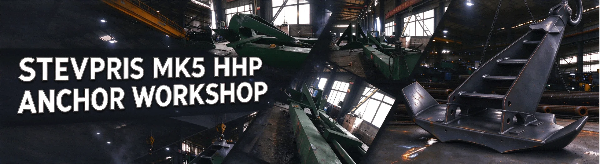
Our Workshop:
1. Verify Manufacturing Capability
Confirm whether the supplier manufactures the anchor directly or coordinates production through qualified manufacturing facilities. Ask about steel fabrication, cutting, forming, welding, dimensional inspection, surface treatment and final assembly. For a large anchor, the supplier should be able to explain how the major components are manufactured, positioned and inspected.
2. Review Drawing and Specification Control
The supplier should work from the correct model designation, approved drawing revision and purchase specification. Changes to dimensions, materials, welding details or connections should be documented and approved by the responsible party before implementation. Unapproved substitutions can affect installation compatibility and structural performance.
3. Check Material Traceability
Ask how the supplier identifies steel materials and links them to certificates and production records. Depending on the order, relevant documents may include material certificates, mechanical test reports and material identification records. The documentation should match the requirements stated in the contract.
4. Evaluate Welding and Fabrication Control
For fabricated anchors, review how welding procedures, qualified personnel, joint preparation and dimensional control are managed. Inspection requirements should reflect the approved design and project specification. Non-destructive testing methods and their acceptance criteria should be agreed in advance where required.
5. Confirm Quality Inspection Arrangements
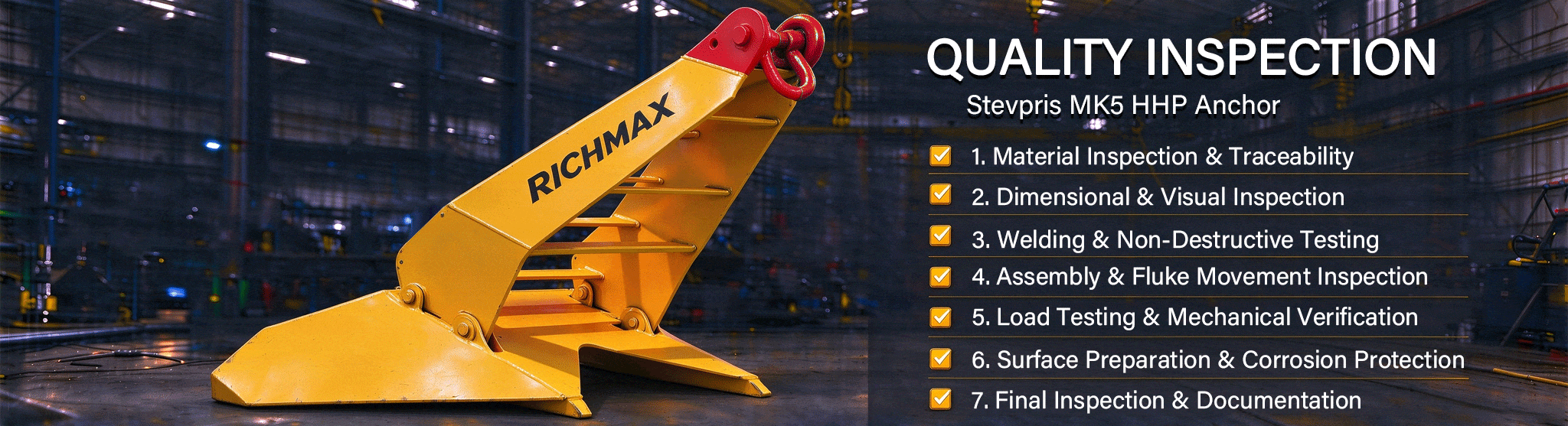
The inspection plan should identify the checks required at each production stage, including material verification, dimensional inspection, visual examination of welds, specified non-destructive testing and final inspection. Where a classification society or independent inspection body is involved, the supplier should confirm the scope, timing and documentation required.
6. Assess Production Coordination and Delivery Control
Large anchors may involve several manufacturing processes or facilities. The supplier should be able to coordinate production progress, inspection arrangements, surface treatment, packing and dispatch. Inspection hold points and document submission dates should be considered when establishing the delivery schedule.
7. Clarify Documentation and After-Sales Responsibility
Before placing an order, establish who is responsible for technical clarification, drawing revisions, inspection findings, corrective action and missing or non-conforming documentation. The supplier should have a clear process for investigating discrepancies and agreeing corrective measures with the purchaser.
Richmax Supply and Quality Coordination
Qingdao Richmax Imp. & Exp. Co., Ltd. supplies marine hardware and marine equipment for international B2B projects. As an affiliated company of Hiking Group Global Industrial Limited, Richmax can coordinate with relevant manufacturing facilities according to the product and project requirements.
For a Stevpris MK5 HHP Anchor enquiry, the supply process can be organized around drawing confirmation, material and fabrication requirements, dimensional control, agreed inspection arrangements and export documentation. The actual manufacturing route, inspection scope, certificates and delivery conditions should be confirmed for each order.
Buyers can provide the required anchor model, drawing, quantity, target delivery date and applicable technical specifications for quotation and technical review.
FAQ
1. What is a Stevpris MK5 HHP Anchor?
A Stevpris MK5 HHP Anchor is a high holding power marine anchor intended for specified anchoring and mooring applications. Its suitability depends on the approved anchor design, seabed conditions, installation method and required holding performance.
2. What does HHP mean in Stevpris MK5 HHP Anchor?
HHP stands for High Holding Power. It describes an anchor category associated with high holding power relative to conventional anchor designs under the applicable evaluation criteria. Actual performance depends on the anchor configuration and operating conditions.
3. What is the main function of a Stevpris MK5 anchor?
Its function is to develop resistance in the seabed and transfer the resulting load through the anchor and its connection into the mooring system. The anchor must be selected and installed according to the system's engineering requirements.
4. Where is the Stevpris MK5 HHP Anchor used?
It may be specified for offshore anchoring, floating-unit mooring and marine engineering projects where the model is accepted by the project design. The application should be confirmed against the anchor's technical documentation and the intended installation conditions.
5. Is the Stevpris MK5 suitable for every seabed type?
No single anchor configuration should be assumed suitable for all seabed conditions. Soil type, strength, layering, slope and installation conditions can affect penetration and holding resistance. Suitability should be established through the relevant engineering assessment.
6. How is the required anchor weight determined?
Anchor weight is determined by the approved design and required system performance. It should not be selected solely from vessel size, water depth or a comparison with another anchor. The mooring-system design and site-specific conditions must be considered.
7. What materials are used to manufacture a Stevpris MK5 HHP Anchor?
The materials depend on the approved drawing and purchase specification. Steel grades, mechanical properties, weldability and any impact-test requirements should be confirmed for the relevant components before production.
8. Can the anchor be manufactured according to customer drawings?
Project-specific supply may be possible, subject to technical review and manufacturing capability. The purchaser should provide the model identification, drawings, material requirements, connection details and inspection specifications. Any proposed deviation should receive approval from the responsible design authority.
9. What inspection is required for a Stevpris MK5 HHP Anchor?
Inspection may include material verification, dimensional checks, visual examination, weld inspection, specified non-destructive testing and final verification. The exact scope depends on the approved design, purchase specification and any classification-society or third-party requirements.
10. Does every Stevpris MK5 anchor require classification-society certification?
Not necessarily. Certification and survey requirements depend on the project, contract, applicable rules and purchaser's specification. Required certificates and inspection involvement should be confirmed before ordering rather than assumed to be the same for every application.

 English
 Español
 Français
 Árabe
 Русский
 Português
 日本語
 한국어
 Dansk
 Nederlands
 Italiano
 Türkçe
 Deutsch
 Prancis
 ไทย
 Tiếng Việt
 हिंदी
 বাংলা
 中文